The Ultimate Guide to Librebooting a Thinkpad T500
Table of Contents
Video Version of this tutorial:
What is Libreboot? #
“Librebooting” a computer is the process of installing the Libreboot boot firmware onto the computer’s boot flash chip, thus overwriting whatever was previously on it. Most commonly, this is done to replace the vendor’s proprietary BIOS or UEFI with Free Software.
Libreboot is a distribution of Coreboot in the same way that Debian is a distribution of GNU/Linux. Coreboot is a Free firmware platform which requires specific configurations for each motherboard and chipset, so it is labor-intensive to port it between boards. Its job is to initialize the system’s hardware and then pass control to a payload. This payload can be something like GRUB or SeaBios.
In the following article, I flash Libreboot with a GRUB2 payload. On my SSD, I have GRUB2 and a GNU/Linux distro installed. When I boot up the system, there is a black screen for a couple seconds, during which the hardware is being initialized. Then an instance of GRUB2 is loaded from the flash chip. This instance then loads GRUB2 on my SSD. Then, finally, that instance of GRUB2 loads the Linux kernel, which loads the rest of my OS.
Although the Coreboot platform itself is Free, most motherboards will still not boot without some nonfree blobs, for various reasons. This means that Coreboot will add the manufacturer’s binary blobs to some of their configurations. As a distro, Libreboot removes some of these blobs, adds a payload to Coreboot, and optimizes some settings which the end user would have to do anyway. This makes installing Libreboot more straightforward than installing stock Coreboot. If installing Coreboot is like installing Arch GNU/Linux, then installing Libreboot is like installing Manjaro.
Until recently (July 2022), Libreboot would remove 100% of the binary blobs, thus having fully Free firmware on the BIOS chip, but also having very poor hardware support, limited mostly to decade-old ThinkPads. They have now adopted a Binary Blob Reduction Policy which permits some blobs for the sake of practicality. Among other reasons, the Libreboot team argues in favor of this by saying that banning blobs in the BIOS firmware encourages manufacturers to move their blobs to other chips that cannot be rewritten, thus making the blobs more difficult to reverse-engineer and replace with Free Software.
Still, many users do want a guaranteed free firmware distro, so the GNU Boot project was forked from the older, 100% free version of Libreboot. The Free Software Foundation’s Respects Your Freedom program, which validates hardware based on whether it can run fully Free Software, for example, would fail a computer running any nonfree blobs in its writable firmware, no matter how small. The Libreboot team, seeing the demand for fully Free firmware, decided to make their own fork of Libreboot called Canoeboot which also removes all blobs(though it has not always had this name).
In summary, Coreboot is a platform for early boot-time hardware initialization that often requires some binary blobs to run. Libreboot is a user-friendly distribution of Coreboot which packages binary blobs only if necessary. Canoeboot is blob-free Libreboot fork run by the same people who run Libreboot. GNU Boot is a blob-free Libreboot fork run by different people than those who run Libreboot and is part of the GNU project.
If I am installing firmware onto a computer which does not require binary blobs to run, such as a ThinkPad T500, then there will be no significant difference between Libreboot, Canoeboot, or GNU Boot. All of them will be 100% Free Software. If I am installing firmware onto a computer that needs a few small blobs, notably the Intel Management Engine, then Libreboot will likely ship some minified versions of those blobs and work fine fine while Canoeboot and GNU Boot will not ship the blobs and have limited or broken features. If I am installing firmware which requires many blobs to run, then none of the 3 will run and I will have to make a custom Coreboot configuration.
Required Materials #
-
Libreboot compatible device
-
Raspberry Pi Pico H or Pico WH
- Official site
- Pick them up for ~$5 from a local electronics store or online
-
7 Female-to-Female Dupont Wires
- Get short cables for signal integrity reasons. I used 10cm cables and they worked fine.
-
Micro-USB cable
-
Functioning desktop or laptop
-
SOIC Clip
- Pomona 5250 for 8-Pin
- Pomona 5252 for 16-Pin
- Read Below to Check for Number of Pins
-
Thermal Paste
- Type doesn’t matter too much but I use Corsair XTM50
-
(Optional): Free Wireless card
Preface #
This guide will demonstrate the installation of Libreboot on a ThinkPad T500. You should be able to use common sense to modify this guide for any Libreboot installation, but I can’t guarantee it. The official Libreboot documentation is the true “Ultimate” guide. For example, here is the official T500 guide. You should also be able to common sense to modify this guide for installing GNU Boot or Canoeboot.
In our guide, we will be physically disassembling our entire ThinkPad T500. In doing so, we will remove 30 or so screws, reapply thermal paste, and pull on fragile cables. If you are not comfortable with electronics, please consider choosing a different model which is not so hard to disassemble. In fact, some of them, even the ones able to run 100% Free Software, can be flashed via software within the operating system and require no disassembly.
Finding Pin Amount #
In some revisions of the ThinkPad T500, the BIOS chip has 8 pins and in others it has 16 Pins. You cannot use an 8 pin clip to flash a 16 pin chip. However, in the T500, you can use a 16-pin clip to flash an 8-pin chip if you ignore the pins that are not connected to anything. I cannot guarantee that there will always be enough space to clip a 16-pin clip to an 8-pin chip in other computer models. Even in the T500, it barely made it.

Before any disassembly, you can check the number of pins in the laptop from your operating system. Run
# dmidecode | grep ROM
It will retun the BIOS ROM size
ROM Size: 4 MB
On the T500, a 4mb ROM means 8 pins and an 8mb ROM means 16 pins. As far as I know, there are no other ROM sizes or pin amounts.
Disassembly #
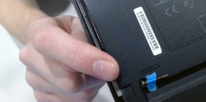
First, pull out the battery.
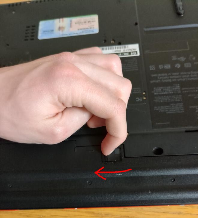
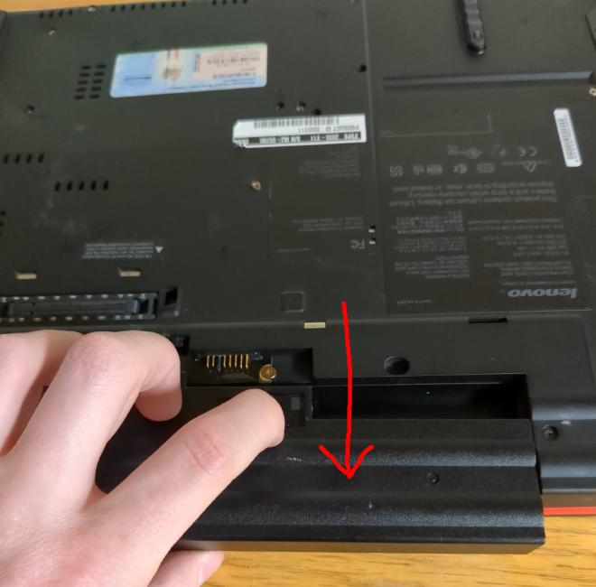
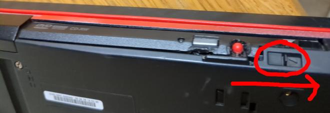
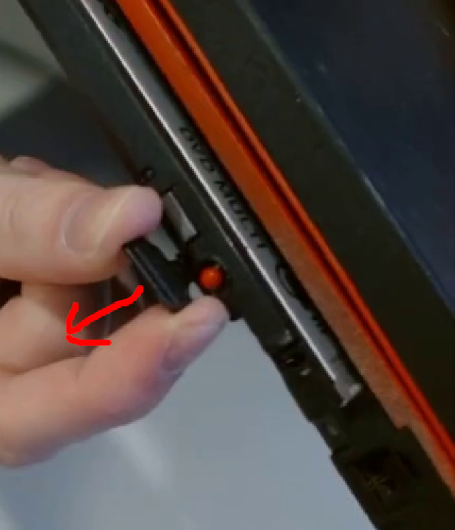
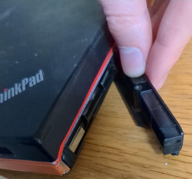
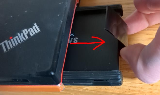
Pull out the disk drive. To pull out the disk drive, flip the switch on the side of it. Then, a tab will pop out. Pull on the tab and the drive will pop loose.
Unscrew the screw holding the SATA drive cage cover on. Then remove the cover to the cage and pull out the SATA drive.
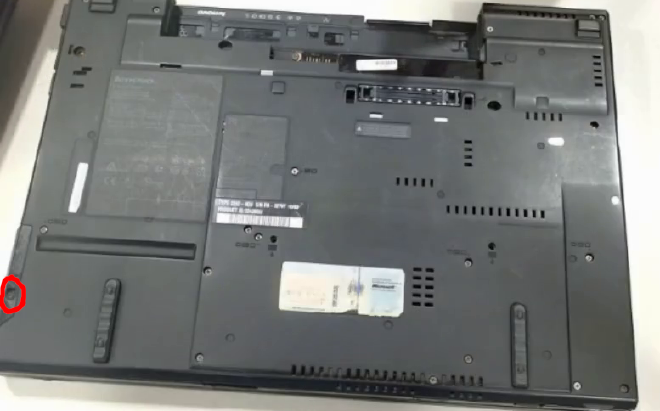
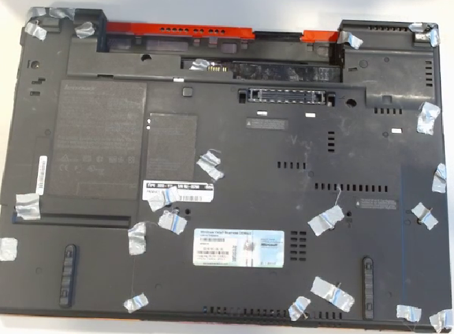
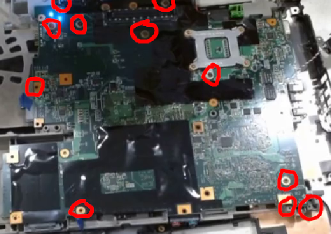
Undo all of the screws on the bottom except for one screw in the middle of the left side of the laptop. Removing it is unnecessary for this guide. If it is removed, the Ethernet bracket and plastic light diffuser may come loose, which are annoying to reattach.
Tech Tip: Keeping Track of Screws #
To ensure that the screws will get returned to their original spot later, tape them right next to the hole where you took them out. Lay the screw flat against the case with the head of the screw halfway in the hole it originally came out of. If you can’t fit it partially back in the original hole, then tape it to the closest thing. Do not tape the screw to the motherboard directly because you may short something. Be sure to use enough tape or they will come off! This also allows you to take your half-assembled laptop on the go without losing the screws.
Remove Miscellaneous Components #
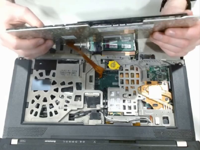
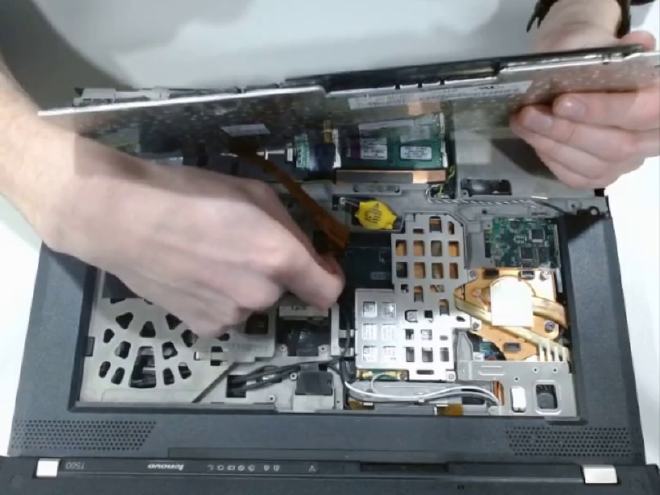
Flip the laptop over (the screws will be fine if you added enough tape). Flip up the palmrest at a 90 degree angle away from the display. Do not tear the ribbon cable and stop if you can feel strong resistance. Pull up on the foam connector at the end of the ribbon cable to remove it. Set the palmrest aside.
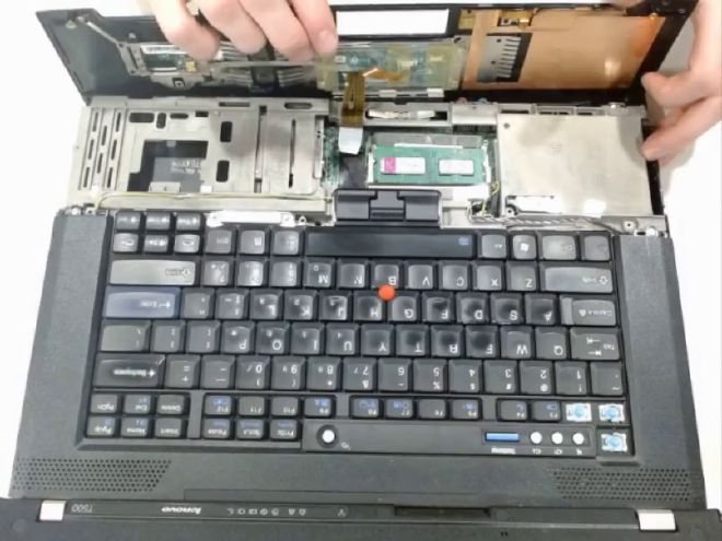
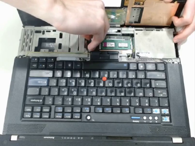
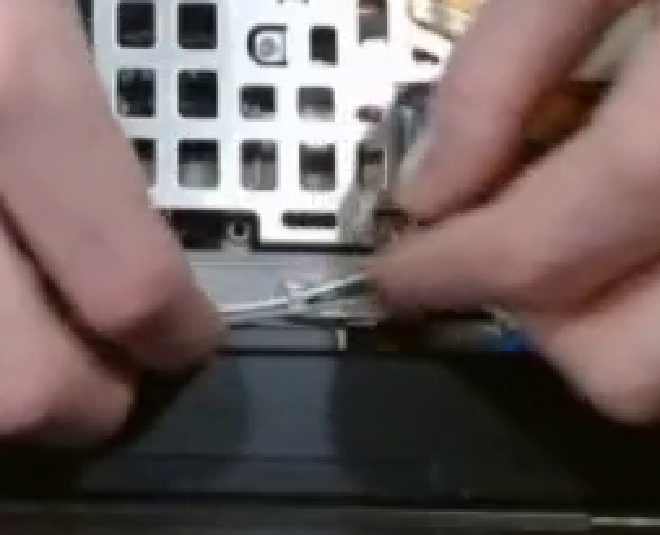
Pull the keyboard up 90 degrees away from the display. This has a similar ribbon cable so do not rip it. The connector is much harder to undo, so you must use your fingernail to pull it up. Put aside the keyboard.
There is a bezel which fits between the keyboard and display. It has a clip which holds some wireless antennas in place. Unplug any antennae from the wireless card and pull the antennae out of the clip. Then, unscrew all 6 screws holding the bezel in place.
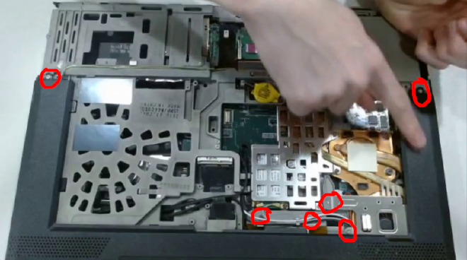
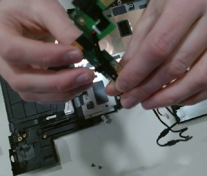
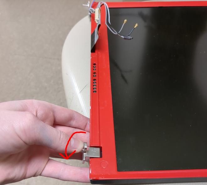
Remove the screw on each of the display’s hinges. Then pull the entire display directly upwards and it will come loose. Then lay it flat. Pull the connector for the ribbon cable straight up to unplug it. On the 8mb revision, you have to wait until after unscrewing the radiation cage to unplug the cable.
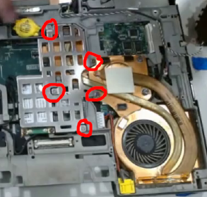
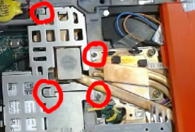
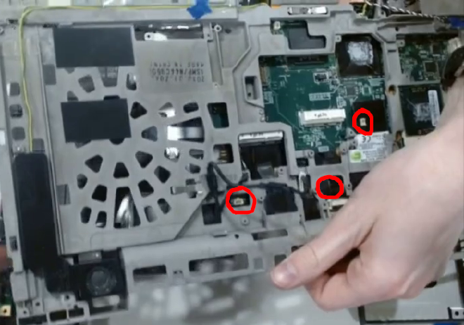
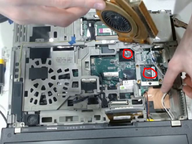
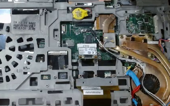
There is a radiation interference shield in approximately the center-left of the board. Remove it. It is covering the WiFi card and shares 2 screws with the CPU cooler. Unscrew those. Depending on the revision of T500, it will have 3 or 2 screws left for you to take out. Remember that through all of this, you should be using tape or another method to keep track of the screws.
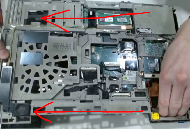
Unscrew the left speaker. The right speaker does not need to come out.
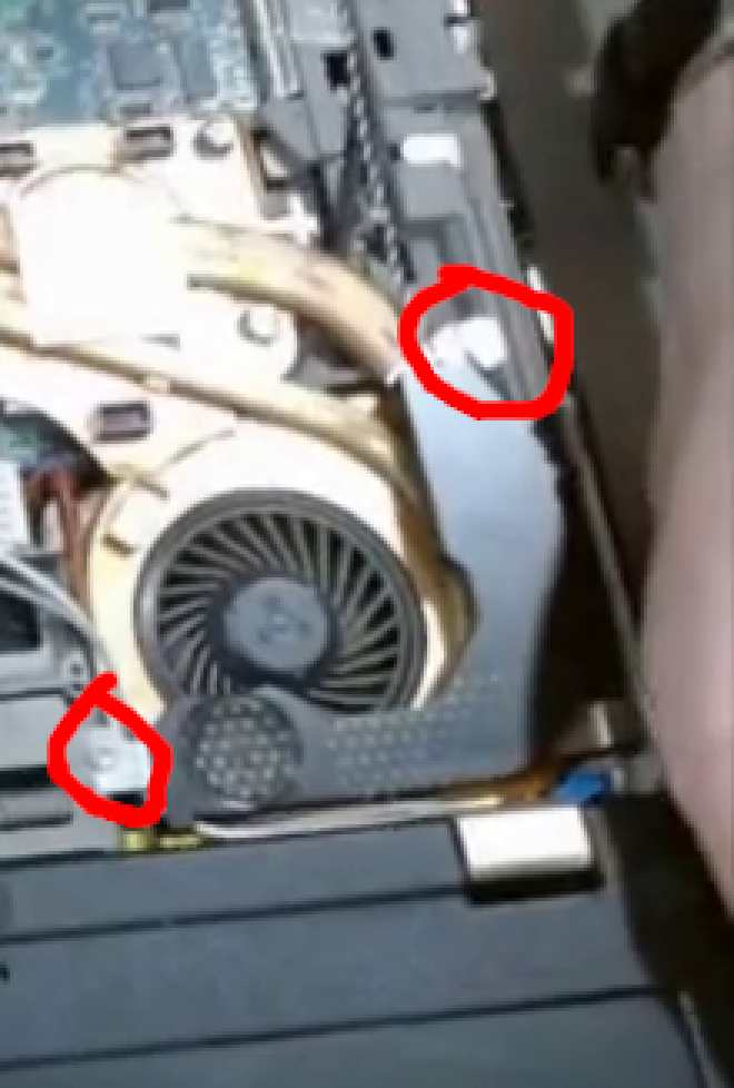
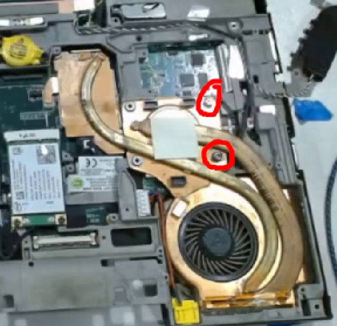
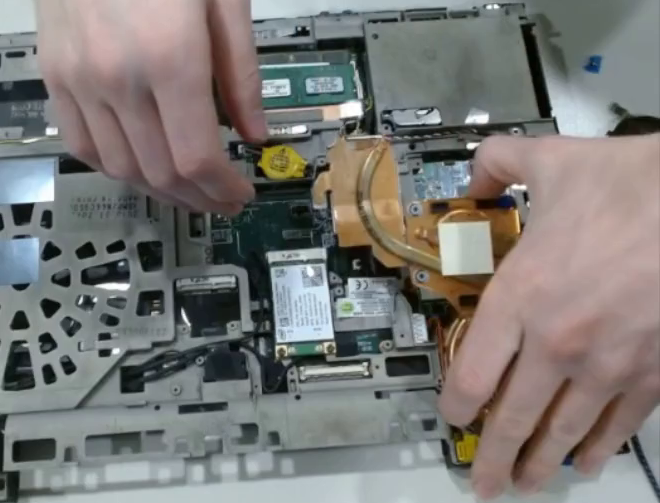
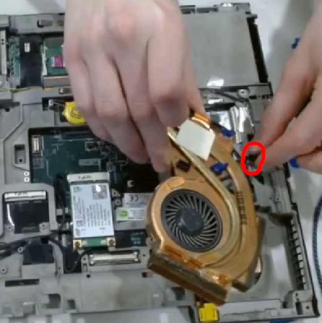
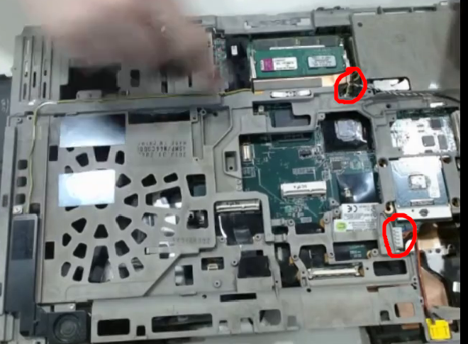
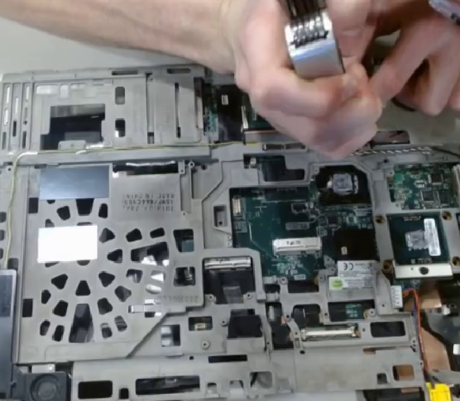
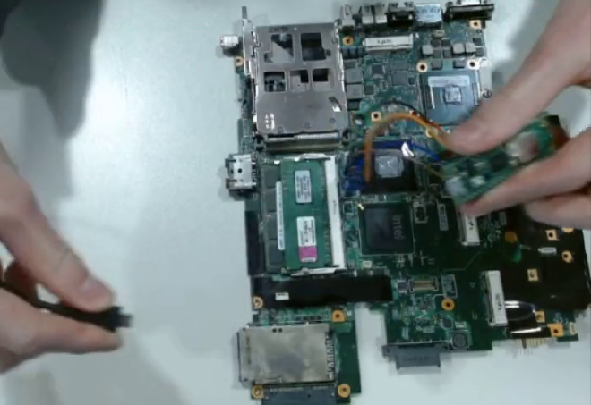
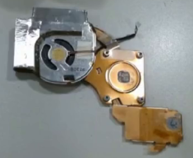
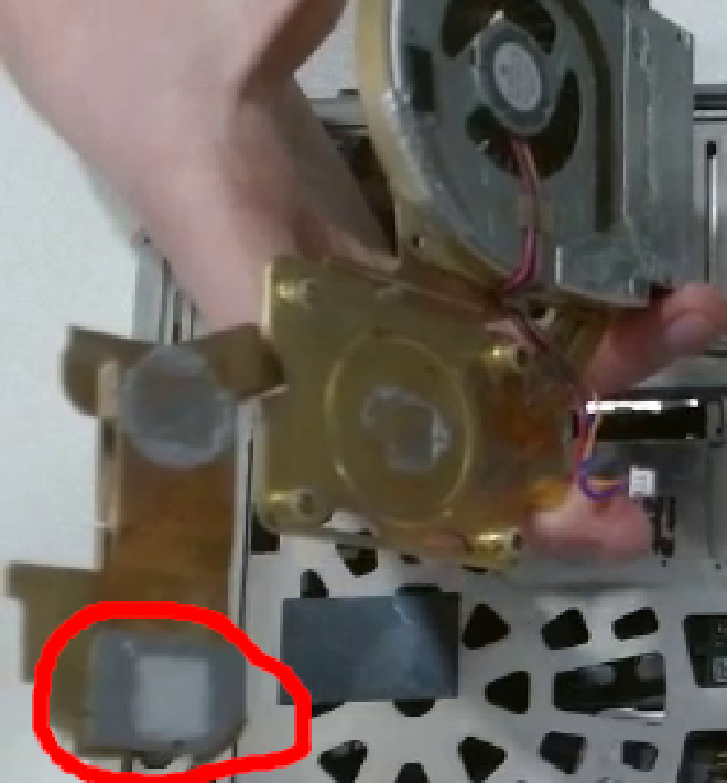
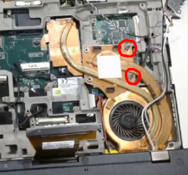
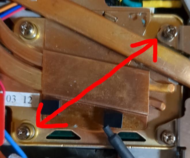
Unplug the CPU cooler. Unscrew the 2 remaining screws. Pull it up at 90 degrees towards the display. The very far end of the cooler towards the keyboard cools the northbridge. It is only attached via a single heatpipe, so if you pull up on this you may bend the heatpipe. Therefore, you should pull using main section of the cooler which is a single copper piece. Also unplug the fan cable.
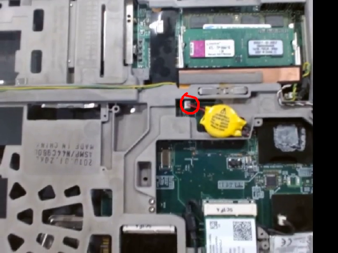
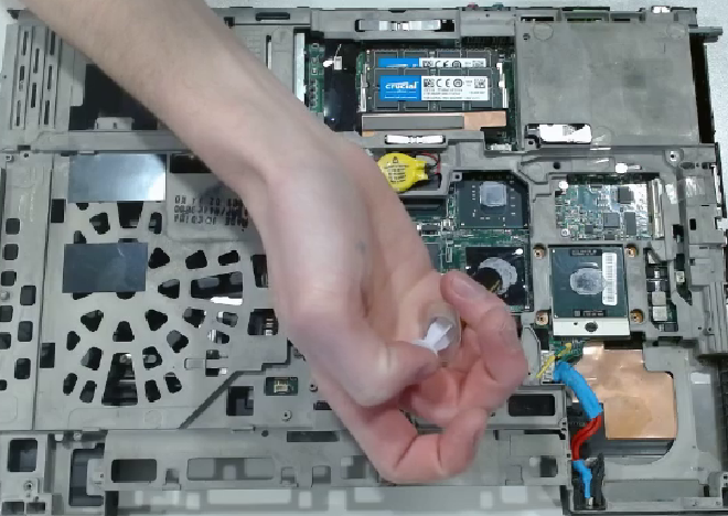
Then pull out the RTC battery. Do not pull exclusively on the wires as they may pop out of their connector. If it helps, use pliers or especially tweezers to pull on the connector.
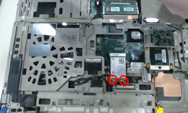
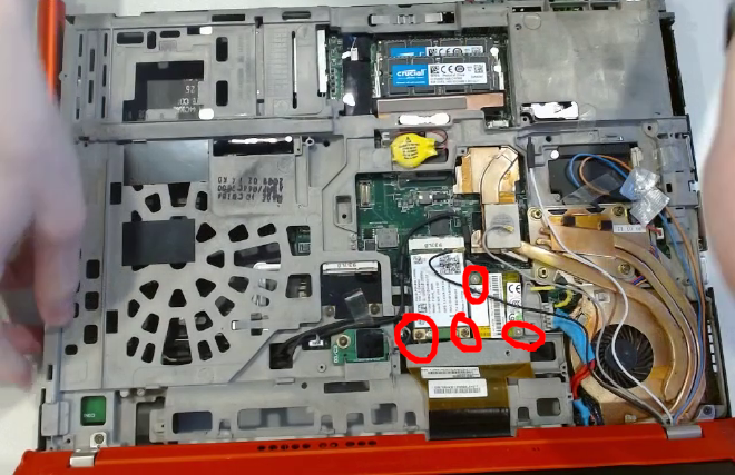
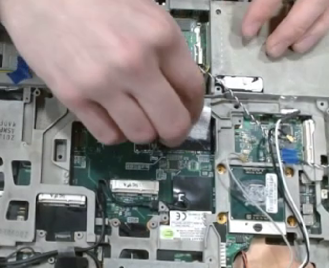
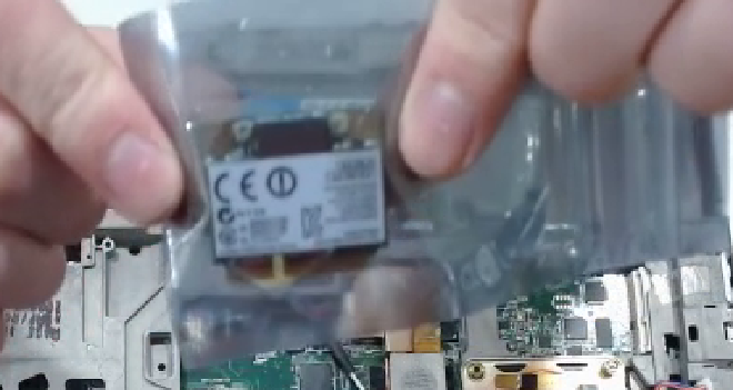
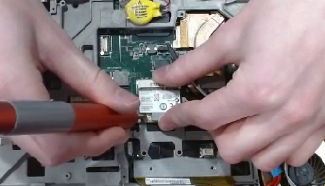
Remove the wireless card by unscrewing both screws and pulling the card horizontally out of the slot. In some T500s, there is a modem card, while in others it is embedded into the motherboard. This was under the radiation cage and next to the WiFi card. If it is a card, then unscrew it and pull it straight up. The connector is on the bottom, out of view.
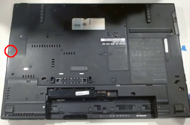
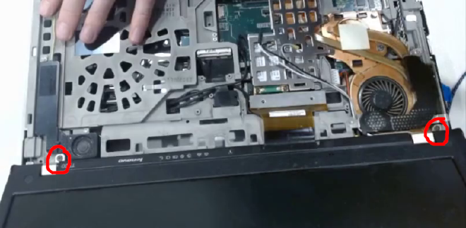
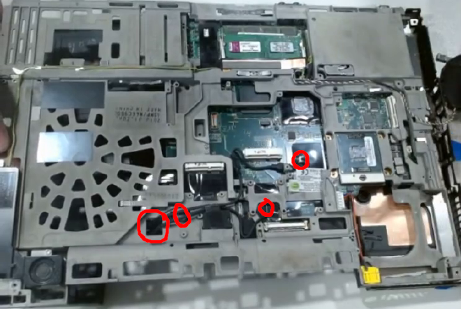
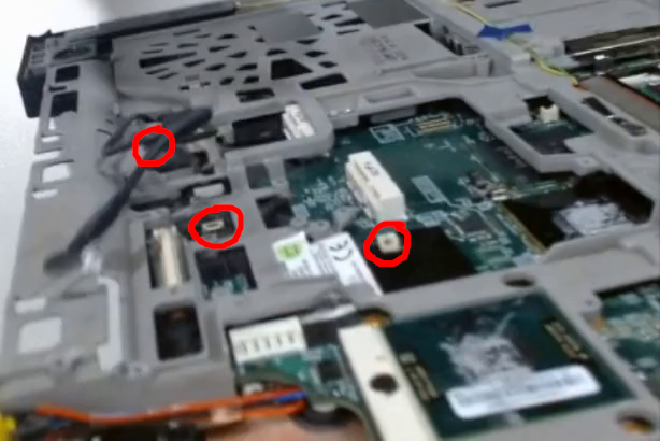
There is a single screw at the very front of the laptop (opposite side as the display) and on the right. It is easy to miss, but unscrew it.
Unplug the power cable which connects the motherboard to the yellow barrel jack. Also unplug the speaker cable, which is located right next to the RAM.
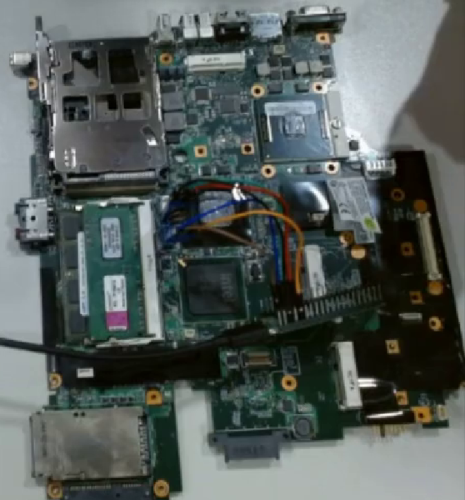
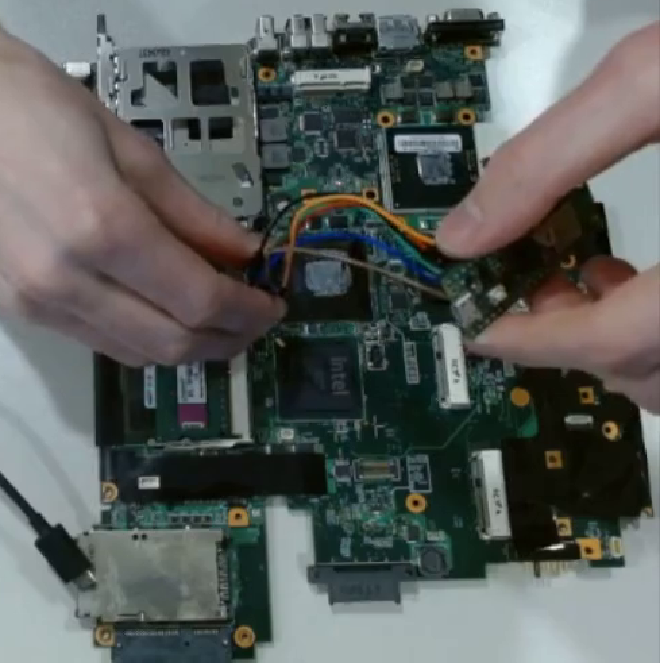
Detach Motherboard #
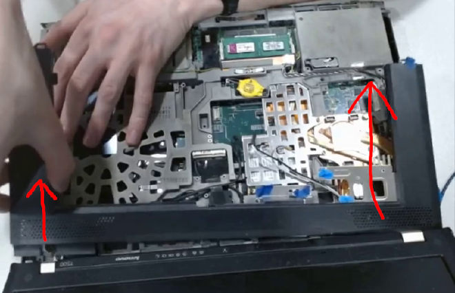
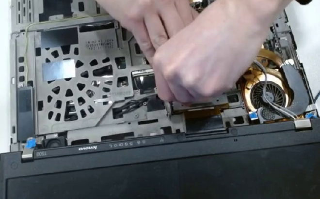
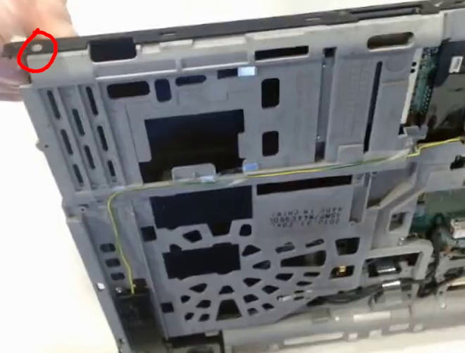
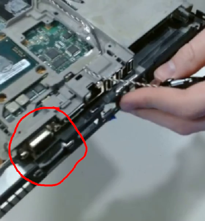
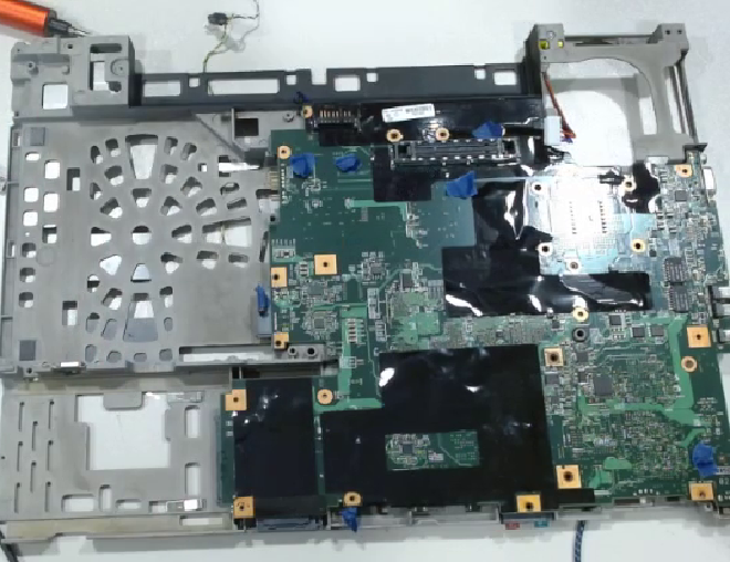
Pull the gray cage up away from the rest of the case and to the right. There is a VGA port in the left I/O and if you only pull straight up it will get caught on the black case.
Now put the black case to the side and lay the gray cage motherboard-side up. Unscrew all the screws. Don’t forget that there is a metal shield surrounding the FireWire port that must be unscrewed.
Pull out the motherboard up until you feel resistance from 3 black cables. If it is not coming out easily, then do not force it. Check that you did not forget any screws.
There is a hole in the gray magnesium allow cage where 3 wires pass through. These ultimately connect to an RJ11 port on the side of the laptop. Unplug all of these cables from the motherboard and thread them through that hole.
Unscrew the power jack as we will need easy access to it later.
Now get onto your existing desktop or laptop.
Install Libreboot #
Install Dependencies #
Install Flashrom and Git
# apt install flashrom git
Initialize Git. If you have done this before the tutorial for other purposes then you do not need to do it again.
$ git config --global user.name “John Doe”
$ git config --global user.email johndoe@example.com
We will be producing and manipulating a number of files. I suggest that you make a folder specifically for this walkthrough.
$ mkdir ~/libreboot
$ cd libreboot
Clone the Libreboot Build System source code
$ git clone https://codeberg.org/libreboot/lbmk.git
$ cd lbmk
Install dependencies. I used GNU/Linux Mint for this tutorial, but replace the name with the current distro that you are using.
# ./build dependencies mint
(Optional) Make Modifications #
Now is the time to make any configurations to the source code. If you want to change the background of GRUB, for example, then overwrite the appropriate file.
$ cp $DESIED_BACKGROUND_1024x768.png config/grub/background/background1024x768.png
$ cp $DESIRED_BACKGROUND_1280x800.png config/grub/background/background1280x800.png
Build ROMs #
Find the ROM type that is appropriate for your machine. To do this type
$ ./build roms list | less
Remember back to when you checked your ROM size with dmidecode
t500_4mb
Compile your ROM. This could take half and hour or so depending on various factors. At some point it will use 100% of CPU resources, but this is normal.
$ ./build roms t500_4mb
Now select your desired ROM.
$ cd bin/t500_4mb
$ ls | grep t500_4mb | less
There will be dozens of ROMS to choose from. Make sure that you choose one with the correct keyboard layout. The keyboard layout is the last section before the .rom file extension. The first two letters are region and the last 5 are layout. I have a United States QWERTY keyboard so I will choose the “usqwerty” layout. The rest doesn’t matter that much, so if you are having trouble picking then choose grub_t500_4mb_libgfxinit_corebootfb… for a standard grub payload.
When you pick a ROM, either remember it or copy it to an easy-to-access location such as the libreboot folder you made.
$ cp grub_t500_4mb_libgfxinit_corebootfb_usqwerty.rom ~/libreboot
Install Flashing Software on Pico #
Now we will compile the flashing software that runs on the Raspberry Pi Pico.
$ cd ~/libreboot/lbmk/
If you have the Pi Pico W (with wireless)
$ ./build serprog rp2040 pico_w
If you have the Pi Pico (without wireless)
$ ./build serprog rp2040 pico
The rest of the tutorial assumes you have the Pi Pico W
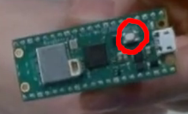
The Pico can connect to your computer in 2 ways when you plug it in with the micro-USB cable. The first way is when it appears as a block device with a filesystem and the other way is when it doesn’t. For now, we need it to appear as a block device with a filesystem. This can be achieved by holding the button on the Pico as you plug it in. I am using GNU/Linux Mint, which will automatically mount filesystems at /media/$CURRENT_USER/ . Depending on your config, you may have to manually mount it.
Copy serprog firmware onto the Pico
$ cd bin/serprog_rp2040/
# cp serprog_pico_w.uf2 /media/$CURRENT_USER/RPI-RP2/
If the Pico immediately unmounts, that is fine and healthy.
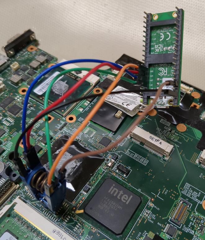
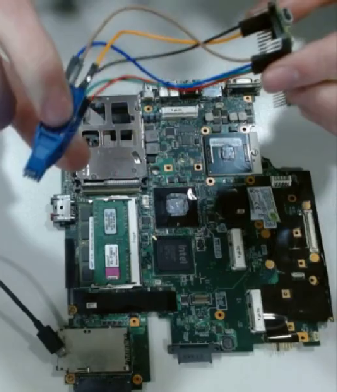
Connecting the Pico to the Board #
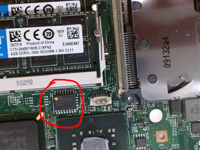
Disconnect your Pico and look for your BIOS chip.
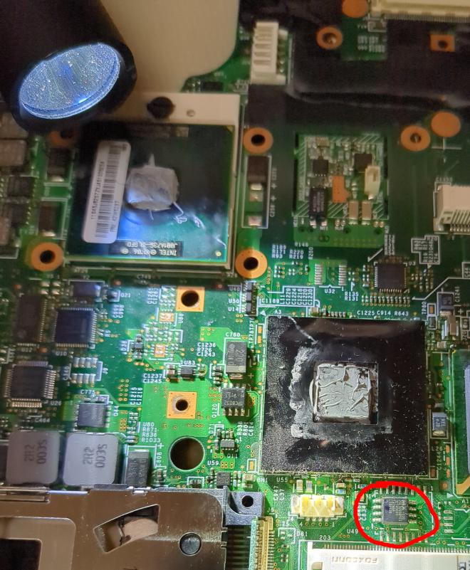
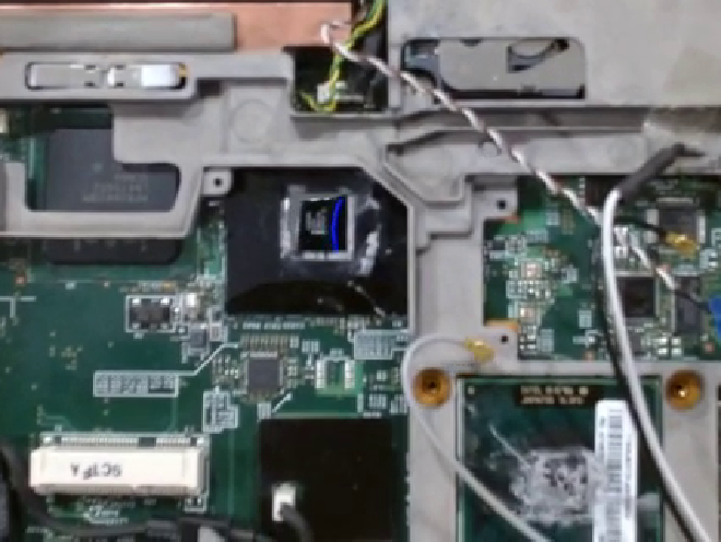
The BIOS chip is located just between the RAM and the northbridge on the T500. There is a model number on it. For the T500, The model number will start with “MX25L” (The logo is part of the model). Write down the number.
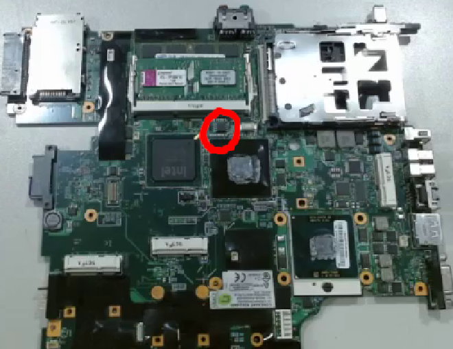
Now we will connect the jumper cables to the clip and Pico. Look for a small circular dimple in one of the corners of your BIOS chip. Ignore any paint or sharpie markings on the chip; only the divet matters. The pin in the corner closest to the dimple is pin 1.
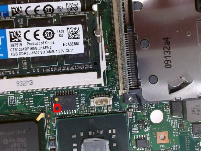
On the 8 pin chip, the dimple is difficult to see. Shine a flashlight sideways to highlight the dimple.
Put your clip onto the chip and remember which pin signifies 1. Now plug a jumper cable into your clip on pin 1.
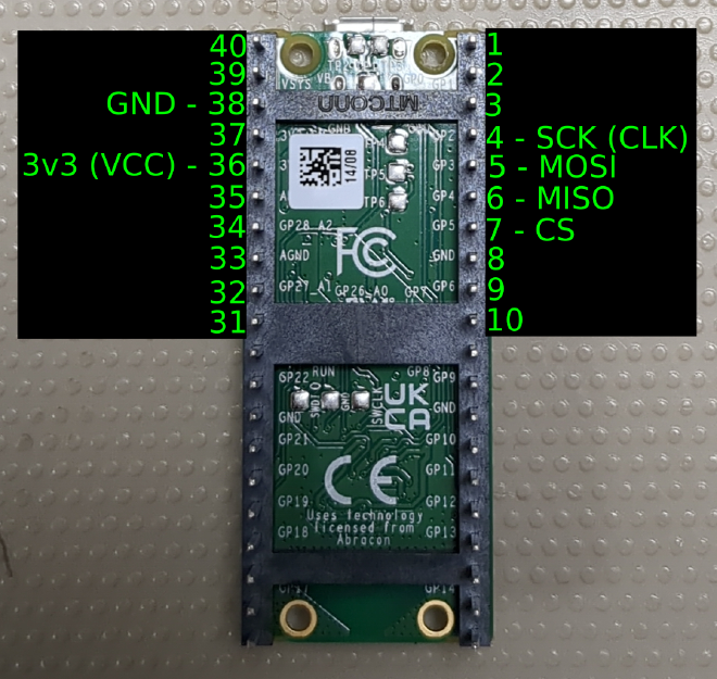
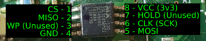
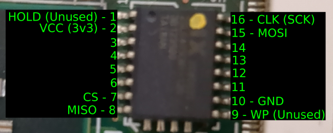
The function of each pin on the chip side depends greatly on the type of BIOS chip that you have. Whereas, the functions of the pins on the Pico do not change. Thus, you must check the diagrams below to match them properly. Check the function of the pin and plug it into the equivalent header on the Pico. Repeat for the rest of the pins. Only 6 of the pins are used.
Connect pins that have the same function.
| Function | Pico Pin Number | 8-Pin Chip Pin Number | 16-Pin Chip Pin Number |
|---|---|---|---|
| SCK/CLK | 4 | 6 | 16 |
| MOSI | 5 | 5 | 15 |
| MISO | 6 | 2 | 8 |
| CS | 7 | 1 | 7 |
| GND | 38 | 4 | 10 |
| 3v3/VCC | 36 | 8 | 2 |
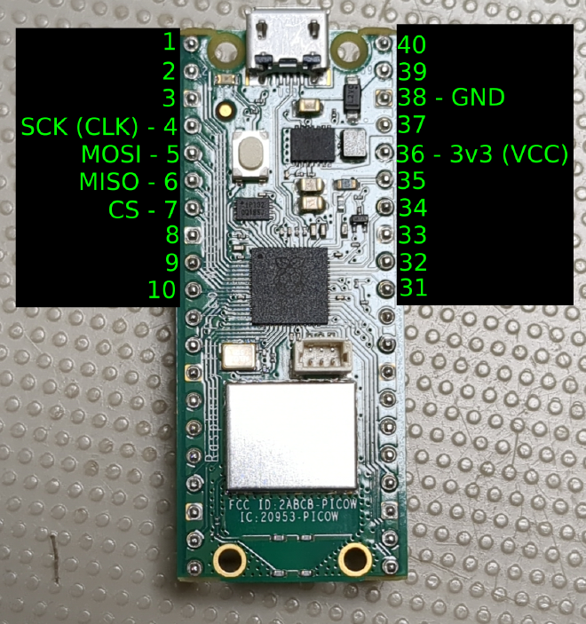
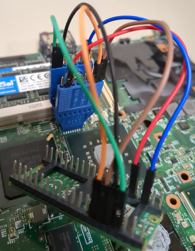
Note that you must never plug in the Pico before connecting the clip. You must always connect the clip with a disconnected Pico or you could corrupt/fry your chip.
Now go back to your laptop/desktop.
Flashing the Chip #
We want to find which serial connection it is using. Run the following command:
$ dmesg -wH
Take note of what the current final line in your dmesg output is. We want the Pico to go in without being detected as a block device. When the Pico connects, dmesg will print information about it.
Now, plug in your Pico without holding the button. Check everything below what was previously the last line of dmesg. Look for a “tty” number
ttyACM0: USB ACM device
Write down the “ACMx” number and then we are ready to flash.
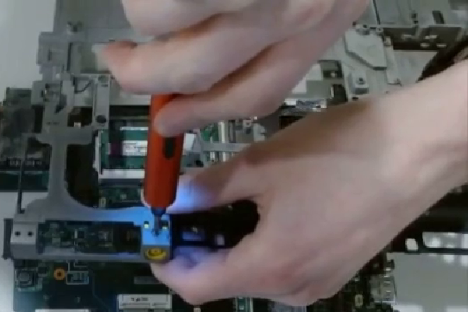
Unplug your Pico, attach the clip to the chip (remember to align it properly relative to pin 1), and then plug in the Pico again.
Now, run the following command and replace “ACMx” with the appropriate number.
# flashrom –p serprog:dev=/dev/ttyACMx,spispeed=16M
It should output:
Multiple flash chip definitions match the selected chip(s)
It will display a list of chip models. Select the model which matches the most amount of characters from the model you wrote down earlier. The number I wrote down was “MX25L3205DM21” and the closest match was “MX25L3205D/MX25L3208D”. Copy that closest match and paste it in the later commands.
Note that if at any point you get the following error:
Note: flashrom can never write if the flash chip isn’t found automatically
Then simply reseat the connection (remember not to attach the clip while the Pico is plugged in via USB).
Now we will read the current BIOS from the chip and back it up in case we want to restore.
# flashrom –p serprog:dev=/dev/ttyACMx,spispeed=16M –c “MX25L3205D/MX25L3208D” –r old_bios.bin
Repeat this process twice more, outputting to different files each time:
# flashrom –p serprog:dev=/dev/ttyACMx,spispeed=16M –c “MX25L3205D/MX25L3208D” –r old_bios2.bin
# flashrom –p serprog:dev=/dev/ttyACMx,spispeed=16M –c “MX25L3205D/MX25L3208D” –r old_bios3.bin
We will compare these 3 files to make sure they are the same. If they are, then we will assume that we had no errors when reading. If they are different, then step back and diagnose the issue. If they are the same then the following commands will have no output.
$ diff old_bios.bin old_bios2.bin
$ diff old_bios2.bin old_bios3.bin
Now we will write to the chip:
# flashrom –p serprog:dev=/dev/ttyACMx,spispeed=16M –c “MX25L3205D/MX25L3208D” –w grub_t500_4mb_libgfxinit_corebootfb_usqwerty.rom
This may take a couple minutes. Do not touch the clip or in any way interrupt the flashing process.
When that finishes, we will read our flashed chip and ensure that it maintained integrity
# flashrom –p serprog:dev=/dev/ttyACMx,spispeed=16M –c “MX25L3205D/MX25L3208D” –r new_bios.bin
$ diff new_bios.bin grub_t500_4mb_libgfxinit_corebootfb_usqwerty.rom
If there is a difference, then diagnose and reflash. It should theoretically be installed now.
Now we will reassemble the laptop just enough to test it.
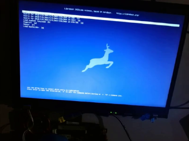
Testing #
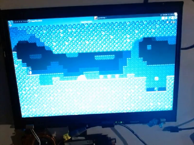
Unplug the USB cable and unclip from the board. Plug in the DC jack, display, and keyboard. Plug in power from the wall and see if the BIOS has been replaced. Optionally, you can plug in the SATA drive and CPU cooler to see if it will run the OS, but even in successful Libreboot installations, sometimes the OS must be reinstalled.
For example, I had a successful Libreboot installation that would not run the Manjaro installation that was installed before the flash. Yet, it would run a Debian installation on a drive that I had taken from another, unrelated, ThinkPad.
Reassembly #
Attach Motherboard to Case #
After it passes your examination, remove the temporary components that you had just added and place the motherboard in the gray magnesium alloy cage. If you used the tape method, then you don’t need to remember where the screws went. Simply take them out of the tape and screw them into the nearest hole. Don’t forget to add back the shield covering the FireWire port. Also screw in the barrel jack again.
Thread the 3 cables connected to the RJ11 port through the hole they originally went through. Then slide the gray cage back into black case, remembering not to get the VGA port stuck.
Plug in those 3 cables. One of them plugs into an obscured port hidden under black tape and it slides in sideways.
Plug in the power jack and speaker cable.
Screw in that one screw on the front of the case.
Drop in the display assembly and then screw it in. If the hinges are misaligned, then the display will not slide it. Thus, you must bend them manually.
Thermal Repaste #
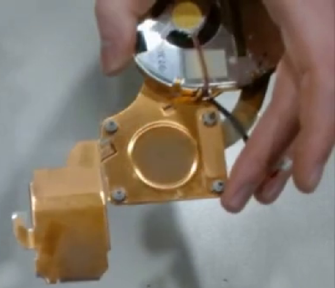
Some T500 variants have ATI discrete GPUs. In these cases, there will be thermal paste on the CPU and GPU. The cooler will have a thermal pad for the northbridge. On other variants, there will be no discrete GPU and there will be thermal paste on the CPU and the northbridge. Because these laptops are so old, the thermal paste has most likely become a crust and must be replaced, especially if the cooler has been removed and reattached.
In both cases, take a paper towel and wipe the 2 chips with old paste on them. They should be clean to the point of looking like a mirror. Any extra paste on the side of the die can be ignored; it will not cause issues. Also wipe the paste off of the cooler, which will not end up so shiny. If, in the discrete GPU variants, the thermal pad is hardened and not rubbery to the touch, it must be replaced. More than likely, though, even after all these years, the thermal pad is probably fine so don’t touch it.
To apply thermal paste, squeeze a grain-of-rice-sized amount of paste onto the die. The process of tightening the CPU cooler later will automatically squeeze the paste and spread it out; you don’t need to do it manually. The type of paste also doesn’t matter, as long as it is a reputable brand.
Partly screw in the two screws on the CPU cooler which are closest to the edge of the laptop. These will be fully tightened later in a special way.
Finishing Touches #
Insert a wireless card. The default Intel card requires nonfree drivers to operate, though there are replacements that accept Free drivers. Slide the card into the mPCIe slot at about a 45 degree angle. Then push it down flat and screw in the two screws.
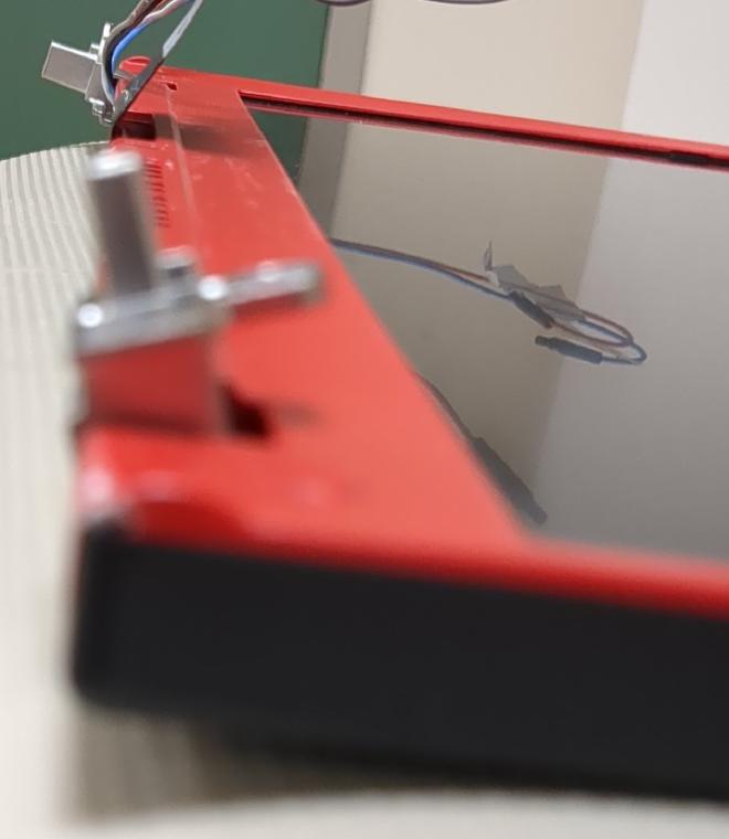
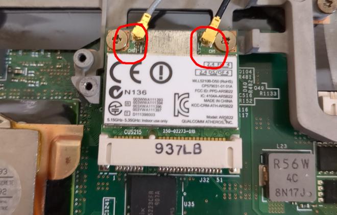
Plug two of the antennae into the WiFi card. On the T500, the gray cable is MAIN, the black cable is AUX, and the white cable is 3rd, though the white is likely unused. Check the manual of your card to determine which cable clips into which port. Typically, MAIN will plug into CH0 on the card and AUX will plug into CH1 on the card.
If desired, reinsert the modem card.
Screw in the wireless interference cage, only partly screwing in the CPU cooler screws.
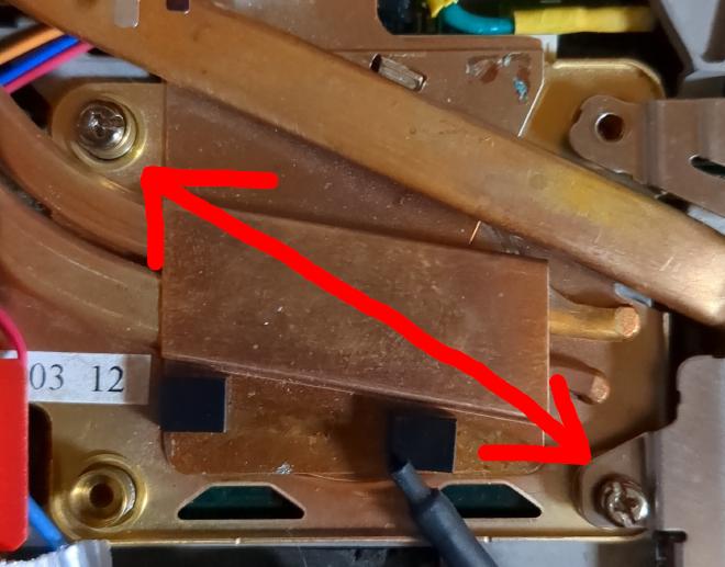
Now we will tighten the CPU cooler screws. We want to make sure the cooler goes down as flat as possible, so we will tighten one diagonal pair of screws at a time. Pick two screws that are on opposite corners as each other. Tighten one a bit, then tighten the other one a bit, then do the first one some more, then the second some more, and continue until they are fully inserted. Repeat this for the other two screws.
Plug in the CPU cooler.
Plug in the RTC battery.
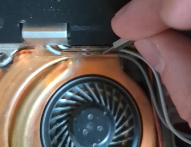
There will be at least 3 antenna cables coming out of the display assembly near the CPU cooler. Push them between the fins on the CPU cooler. Use a thin object like a paper clip to push them all the way down such that they reach the latches that hold them in place.
Screw in the left speaker.
Slide the keyboard bezel into place, push it down, and screw all 6 screws in. Clip the antennae into the clip that sits on top of the video cable.
Plug in the keyboard cable. Slide the keyboard into place.
Plug the trackpad keyboard into place. Snap the palmrest into place.
Close the display and flip over the case. Slide in the SATA drive and then put the drive slot cover on. Slide in the CD drive. Screw in everything on the bottom.
Plug in the main battery.
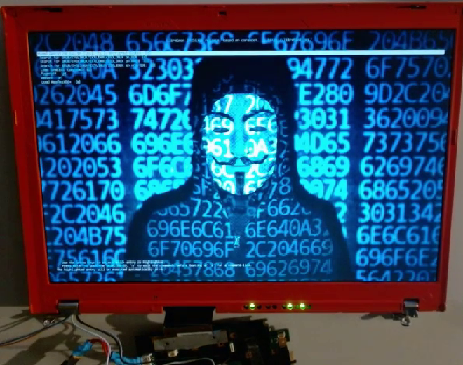
Finished #
Congratulations! You now have a Librebooted Thinkpad. If you then install a fully Free GNU/Linux distro or some sort of BSD, then you will have a computer which has been purged of nonfree software.